Electrical
Safe Instrutions.
Safety to be taken during the work of Electrical
1) There are Rubber handles in hand.
2) Rubber boots should be installed at the base station.
3) Apply wooden sticks to the place where you work.
4) Whenever we check light it is safe to check whether it is safe or not.
5) Whether the grip is tight in the grip or not it is checked.
6) First of all, switch off the main switch with the first task and set someone there.
7) Select the switch according to load.
8) Clean the place where the work is done.
9) Do not have water contact in the place where it works.
10) At the time of doing work, all the tools should be taken together.
Introduction of literature

 1) Hammer: - The use of hammer is used for fitting and striking fittings in switch board.
 2) Scrubeyur: - The time at which we put the board or used in Kacing capping.
 3) Drill machine: - Drill machine is used for holes .And they all have different drill bits. That is, the bits of plywood and concrete are different.
 4) AXA Blade : - It is used to cut the strip. The board has to be cut to put in the board.
 5) Cutter : - Cutter is used to weld the wire.
 6) Spanner set : - Due to the spanner, you can open the motor.There are all kinds of spinners.
.
 7) Soldering guns : - With softening guns, we can do the wintering and the de-soldering can be done.
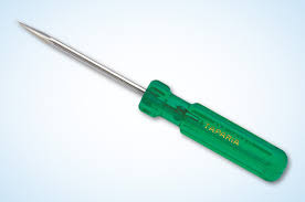
 8) Tester : - Tester is used to check current. When you do wiring, you do a quick check before it.
Types of wire
Purpose : - Practice the wire type.
Material: - All types of wire (e.g. 1) Single core wire (2) to core wire (3) 3 core wire (4) four core wire (5) multistand wire ..
1) Single core wire: - It is made from aluminum. This wire is used to carry phage, new, earthing, earth flow.

2) Two-core wire: - It is used for carrying out the flow of wire and noise . It also has wire aluminum and multistandards

3) Three Core Wire: - If the wire wants sense for your machine, then use three core wires. This phase wire and nutrala and that earthing is nehnya to carry viduyata flow.

4) Four core wire: - This wire can also be used for phase 2 nu2, or three phase one nutle.

5) Multistand Wire: - This wire is flexible. Wire is made of copper and this wire uses more wiring in the house.

Electrical Symbols & Electronic Symbols
Electrical symbols and electronic circuit symbols are used for drawing schematic diagram.
The symbols represent electrical and electronic components
 8) Tester : - Tester is used to check current. When you do wiring, you do a quick check before it.
Types of wire
Purpose : - Practice the wire type.
Material: - All types of wire (e.g. 1) Single core wire (2) to core wire (3) 3 core wire (4) four core wire (5) multistand wire ..
1) Single core wire: - It is made from aluminum. This wire is used to carry phage, new, earthing, earth flow.

2) Two-core wire: - It is used for carrying out the flow of wire and noise . It also has wire aluminum and multistandards
3) Three Core Wire: - If the wire wants sense for your machine, then use three core wires. This phase wire and nutrala and that earthing is nehnya to carry viduyata flow.
4) Four core wire: - This wire can also be used for phase 2 nu2, or three phase one nutle.
5) Multistand Wire: - This wire is flexible. Wire is made of copper and this wire uses more wiring in the house.

Electrical Symbols & Electronic Symbols
Electrical symbols and electronic circuit symbols are used for drawing schematic diagram.The symbols represent electrical and electronic components
| Symbol | Component name | Meaning |
|---|---|---|
| Wire Symbols | ||
| Electrical Wire | Conductor of electrical current | |
| Connected Wires | Connected crossing | |
| Not Connected Wires | Wires are not connected | |
Switch Symbols and Relay Symbols | ||
| SPST Toggle Switch | Disconnects current when open | |
| SPDT Toggle Switch | Selects between two connections | |
| Pushbutton Switch (N.O) | Momentary switch - normally open | |
| Pushbutton Switch (N.C) | Momentary switch - normally closed | |
| DIP Switch | DIP switch is used for onboard configuration | |
| SPST Relay | Relay open / close connection by an electromagnet | |
| SPDT Relay | ||
| Jumper | Close connection by jumper insertion on pins. | |
| Solder Bridge | Solder to close connection | |
Ground Symbols | ||
| Earth Ground | Used for zero potential reference and electrical shock protection. | |
| Chassis Ground | Connected to the chassis of the circuit | |
| Digital / Common Ground | ||
Resistor Symbols | ||
| Resistor (IEEE) | Resistor reduces the current flow. | |
| Resistor (IEC) | ||
| Potentiometer (IEEE) | Adjustable resistor - has 3 terminals. | |
| Potentiometer (IEC) | ||
| Variable Resistor / Rheostat (IEEE) | Adjustable resistor - has 2 terminals. | |
| Variable Resistor / Rheostat (IEC) | ||
| Trimmer Resistor | Preset resistor | |
| Thermistor | Thermal resistor - change resistance when temperature changes | |
| Photoresistor / Light dependent resistor (LDR) | Photo-resistor - change resistance with light intensity change | |
Capacitor Symbols | ||
| Capacitor | Capacitor is used to store electric charge. It acts as short circuit with AC and open circuit with DC. | |
| Capacitor | ||
| Polarized Capacitor | Electrolytic capacitor | |
| Polarized Capacitor | Electrolytic capacitor | |
| Variable Capacitor | Adjustable capacitance | |
Inductor / Coil Symbols | ||
| Inductor | Coil / solenoid that generates magnetic field | |
| Iron Core Inductor | Includes iron | |
| Variable Inductor | ||
| Power Supply Symbols | ||
| Voltage Source | Generates constant voltage | |
| Current Source | Generates constant current. | |
| AC Voltage Source | AC voltage source | |
| Generator | Electrical voltage is generated by mechanical rotation of the generator | |
| Battery Cell | Generates constant voltage | |
| Battery | Generates constant voltage | |
| Controlled Voltage Source | Generates voltage as a function of voltage or current of other circuit element. | |
| Controlled Current Source | Generates current as a function of voltage or current of other circuit element. | |
Meter Symbols | ||
| Voltmeter | Measures voltage. Has very high resistance. Connected in parallel. | |
| Ammeter | Measures electric current. Has near zero resistance. Connected serially. | |
| Ohmmeter | Measures resistance | |
| Wattmeter | Measures electric power | |
Lamp / Light Bulb Symbols | ||
| Lamp / light bulb | Generates light when current flows through | |
| Lamp / light bulb | ||
| Lamp / light bulb | ||
Diode / LED Symbols | ||
| Diode | Diode allows current flow in one direction only - left (anode) to right (cathode). | |
| Zener Diode | Allows current flow in one direction, but also can flow in the reverse direction when above breakdown voltage | |
| Schottky Diode | Schottky diode is a diode with low voltage drop | |
| Varactor / Varicap Diode | Variable capacitance diode | |
| Tunnel Diode | ||
| Light Emitting Diode (LED) | LED emits light when current flows through | |
| Photodiode | Photodiode allows current flow when exposed to light | |
| Transistor Symbols | ||
| NPN Bipolar Transistor | Allows current flow when high potential at base (middle) | |
| PNP Bipolar Transistor | Allows current flow when low potential at base (middle) | |
| Darlington Transistor | Made from 2 bipolar transistors. Has total gain of the product of each gain. | |
| JFET-N Transistor | N-channel field effect transistor | |
| JFET-P Transistor | P-channel field effect transistor | |
| NMOS Transistor | N-channel MOSFET transistor | |
| PMOS Transistor | P-channel MOSFET transistor | |
| Misc. Symbols | ||
| Motor | Electric motor | |
| Transformer | Change AC voltage from high to low or low to high. | |
| Electric bell | Rings when activated | |
| Buzzer | Produce buzzing sound | |
| Fuse | The fuse disconnects when current above threshold. Used to protect circuit from high currents. | |
| Fuse | ||
| Bus | Contains several wires. Usually for data / address. | |
| Bus | ||
| Bus | ||
| Optocoupler / Opto-isolator | Optocoupler isolates connection to other board | |
| Loudspeaker | Converts electrical signal to sound waves | |
| Microphone | Converts sound waves to electrical signal | |
| Operational Amplifier | Amplify input signal | |
| Schmitt Trigger | Operates with hysteresis to reduce noise. | |
| Analog-to-digital converter (ADC) | Converts analog signal to digital numbers | |
| Digital-to-Analog converter (DAC) | Converts digital numbers to analog signal | |
| Crystal Oscillator | Used to generate precise frequency clock signal | |
| Antenna Symbols | ||
| Antenna / aerial | Transmits & receives radio waves | |
| Antenna / aerial | ||
| Dipole Antenna | Two wires simple antenna | |
| Logic Gates Symbols | ||
| NOT Gate (Inverter) | Outputs 1 when input is 0 | |
| AND Gate | Outputs 1 when both inputs are 1. | |
| NAND Gate | Outputs 0 when both inputs are 1. (NOT + AND) | |
| OR Gate | Outputs 1 when any input is 1. | |
| NOR Gate | Outputs 0 when any input is 1. (NOT + OR) | |
| XOR Gate | Outputs 1 when inputs are different. (Exclusive OR) | |
| D Flip-Flop | Stores one bit of data | |
| Multiplexer / Mux 2 to 1 | Connects the output to selected input line. | |
| Multiplexer / Mux 4 to 1 | ||
| Demultiplexer / Demux 1 to 4 | Connects selected output to the input line. | |
No comments:
Post a Comment